Due to current market conditions, we have suspended online orders.
Due to current market conditions, we have suspended online orders.
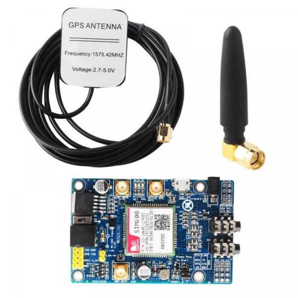
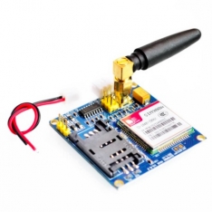
SIM808 module is a GSM and GPS two-in-one function module. It is based on the latest GSM/GPS module SIM808 from SIMCOM, supports GSM/GPRS Quad-Band network and combines GPS technology for satellite navigation. It features ultra-low power consumption in sleep mode and integrated with charging circuit for Li-Ion batteries, that make it get a super long standby time and convenient for projects that use rechargeable Li-Ion battery. It has high GPS receive sensitivity with 22 tracking and 66 acquisition receiver channels. Besides, it also supports A-GPS that available for indoor localization. The module is controlled by AT command via UART and supports 3.3V and 5V logical level.
Availability: In Stock

SIM808 Module GSM GPRS GPS Development Board IPX SMA with GPS Antenna for Raspberry Pi Support 2G 3G 4G SIM Card
Description:
1.Three power input interface: DC044 interface and V_IN and a lithium battery interface.
Note that: The range of DC044 and the V_IN pin voltage input is 5 - 26V, when use the 5V as the power, be sure that the power supply can provide 2A current. The range of voltage of Lithium battery input power is 3.5 - 4.2V.
2. Switch: It is used to open / close the input power supply for the module. When in use, please confirm the toggle switched to the OPEN state (near the board inside).
3. SMA antenna interface: there is a GSM antenna interface, a GPS antenna interface onboard and a BT antenna interface.
4. Start button: When the board is power on, the LED (PWR) will light up. After a long press (about 2 second) on this button, the other three LEDs will be light. And one of them starts to flash; this suggests that SIM808 is beginning to work now. When the power supply, GSM and GPS antenna and SIM card are connected to the module correctly, the LED will be flash slowly (3Second de 1second light), that indicates that the module is registered to the network, and you can make a call or do something else.
5. TTL serial interface: a TTL level interface. Notice that: The pin of VMCU is used to control the high level of TTL UART, so as to realize to match between 1.25V/3.3V /5V systems. For example, if you want to use the 51 MCU to control this board, the pin of VMCU should be connected the DC5V. And if use the STM32 MCU, the pin of VMCU should be connected the DC3.3V. The pins of RXD is the RXD of SIM808 and the pins of TXD is the TXD of SIM808. The pin of V_IN can connect the Power, the function of this pin has the same function of DC044.
6. USB interface: This interface is just use to update the firmware of SIM808 module.
Operation Description:
1. Preparation:
SIM808 SHIELD
DC9V adapter
USB-TTL module or other tools.
PC software
2. Hardware configurations
2.1 Connect the USB-TTL to the UART interface
USB-TTL SIM808
TXD RXD
RXD TXD
GND GND
2.2 Insert the valid SIM card to the SIMCARD holder.
2.3 Connect the GPS antenna and GSM antenna to the board
Connect the power adapter to the DC044 Interface
2.4 Change the switch
2.6 Press the POWKEY button for 2 second, the SIM808 module will work and the other 3 LEDs will light.
Document Link:https://www.adrive.com/public/P7QRkq/FZ1735-SIM808%20%E5%A4%A7V3.1.rar
Package Included:
1 X SIM808 Moudle
1 X GSM Antenna
1 X GPS Antenna